Overview
Fused Deposition Modeling (FDM), sometimes called Fused Filament Fabrication (FFF), puts down thin layers of thermoplastic filament to build up three dimensional forms based on digital designs. Thermoplastic filaments include PLA, ABS, PET, TPU, HIPs and others. There is a variety of types and colors to chose from.
Prints will have nice surface finishes and be full solid color, however this method of 3D printing results in brittle parts that are not sustainable for mechanical parts.
Any 3D modeling program can be used to for the design. The design must then be exported to .STL format to load into a slicing program. The slicing program specific for the FlashForge line of 3D printers is FlashPrint and it is available on all computers in the Arts & Technology Center
The FlashForge Inventor model has dual extrusion heads and a build volume of 230L x 150W x 160H mm
Using FlashPrint Slicing Software
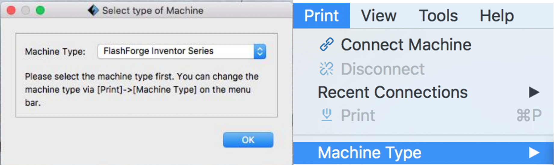
When you open the FlashPrint for the first time a window will pop up asking what type of machine you are using. It is critical that you select the FlashForge Inventor. If you do not select the mahcine type here you will have to Print > Machine Type > FlashForge Inventor.
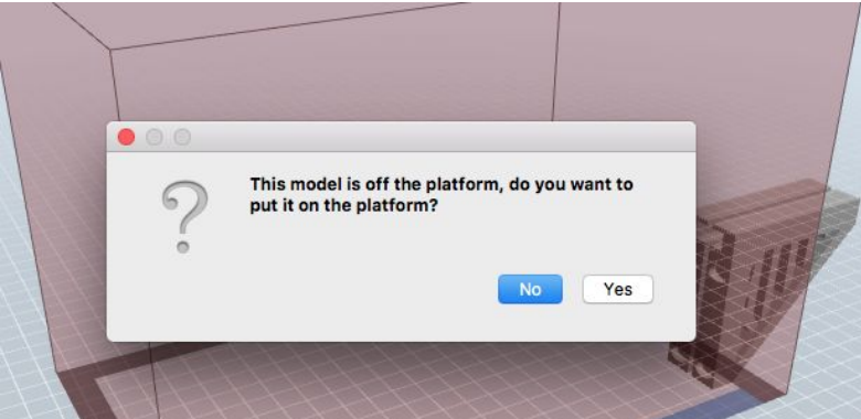
Load the .STL file. Note that there are two possible errors that commonly occur. If the model is not on the build platform select okay to relocate the object so its entirely within the build area.
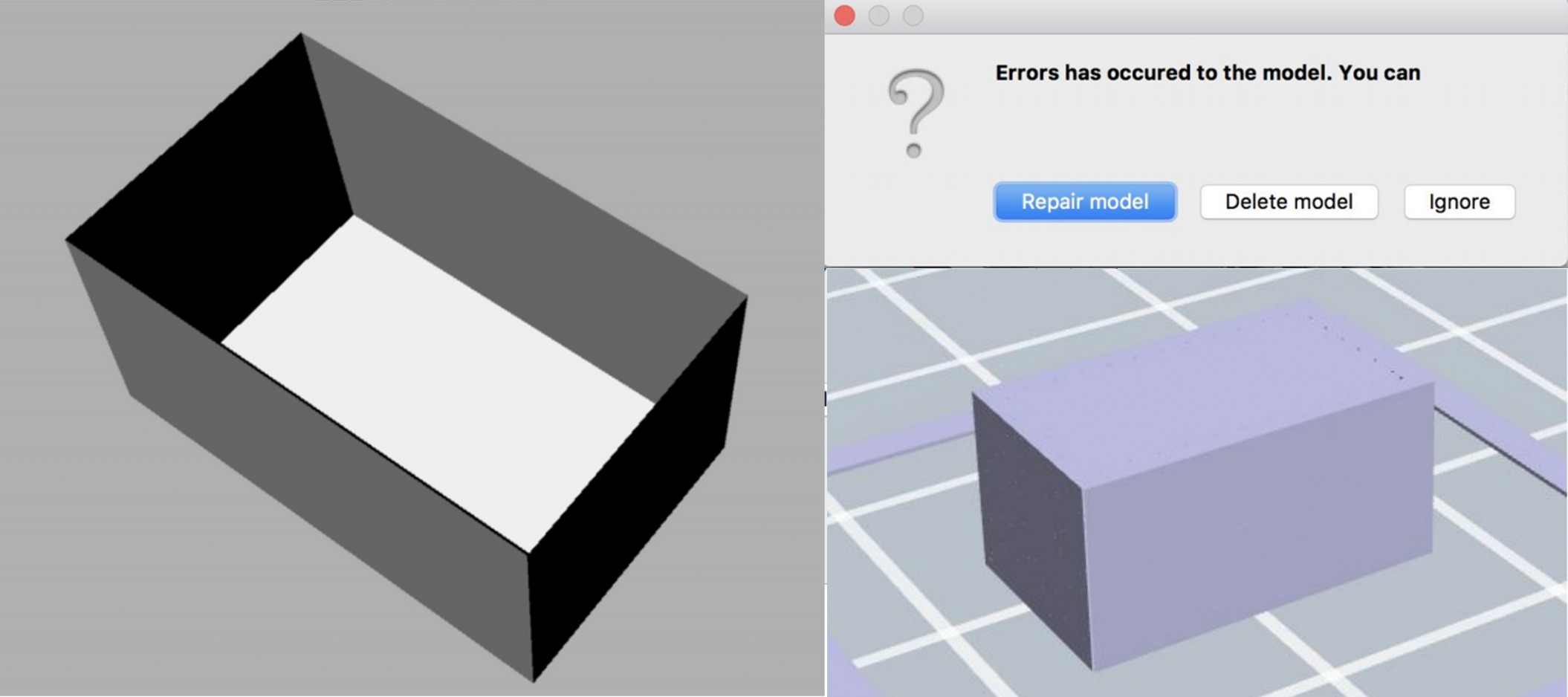
The other pop up states there is an error in the model. You are given the option to repair the model, delete, or ignore. Errors are usually caused when 2D surfaces are loaded, rather than 3D volumes. In the example below the shell of surfaces is automatically filled in based on the 'repair'. Sometimes the repair will just fill in voids, other times it will call extreme issues with the model, possibly make portions disappear, and complicate surface finishes. It is recommended that you investigate the issue in the program you originally created the design and make a repair there.
Move, Scale, and Rotate
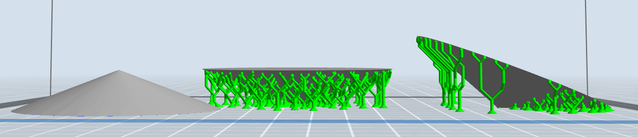
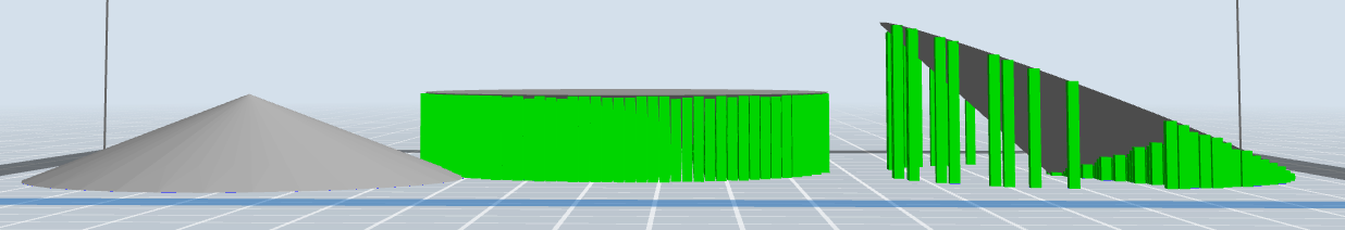
If the model is selected and you double click on scale you will have the option to enter set values for height, width, or depth. Additionally you can scale by percentage or preform a quick translation between inches and mm. See below for examples of how different the supports would be with the cone example in different orientations.
Beyond setting the right scale of a design 3D Printing can be optimize by arrangement and orientation on the printing bed. Consider that there is less strength between layers and some details are best when printed in certain ways.
Supports
With FDM printing, each layer is printed as a set of heated filament threads which adhere to the threads below and around it. Each thread is printed slightly offset from its previous layer. This allows a model to be built up to angles of 45°, allowing prints to expand beyond its previous layer’s width.
As a general rule overhangs need supports if the angle is greater than 45 degrees
FlashPrint has two types of support options, linear and treelike. Default tree like support options are very difficult to remove on small prints, however if you change the settings they can be much simpler to remove and use significantly less filament.
Dual Extrusion Options
The FlashForge has two extrusion heads. If you are doing a multicolor print or printing two objects using different materials make sure to select the wall option. This builds a thin barrier around the objects to basically wipe the nozzle. This is required if not, there's pretty much no point doing a dual extrusion print as the two colours will contaminate eachother due to leakage.
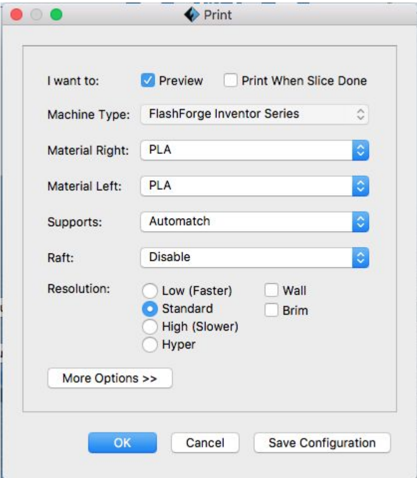
Export for Print
Confirm Flash Forge Inventor is the machine type. Select PLA (or other appropriate) material, but
note that most filament we provide is PLA.
Automatch supports is the default, it means that the same filament will be used for the supports as the actual
object
Select from the resolution options, keep in mind that higher resolutions will have longer print times.
Low 0.3mm
Standard 0.18mm
High 0.12mm
Hyper 0.08mm (Only available with PLA)
Brim and Rafts
A Brim is a good option for more lateral support at the base of an object, its also always necessary with tree like supports that are touching the build platform. Especially for tall objects that are relatively thin at the bottom a brim will prevent many printing errors
A Raft is a layer of filament printed as a base, also extends beyond edge of print and adds support. Rafts are primarily used with ABS to help with warping and bed adhesion, but they can also be used to help stabilize models with small footprints, or to create a strong foundation on which to build the upper layers of your part.
Click OKAY and save to the SD card.

Equipment Overview
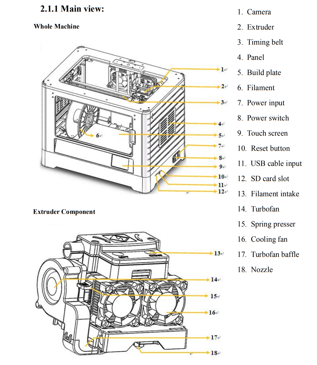
Loading Filament
Filament must pass through the extruder and into the heating block in order to be
melted. In this user guide, we will demonstrate loading and unloading filament using
the left side extruder.
Remove the lid of the Inventor. Remove the filament roll from the sealed container and make sure to put the lid tightly back on.
Make sure there are not tangles in the roll and place it on the red holder outside of the inventor. Then gently feed the filament through
the white tubing.
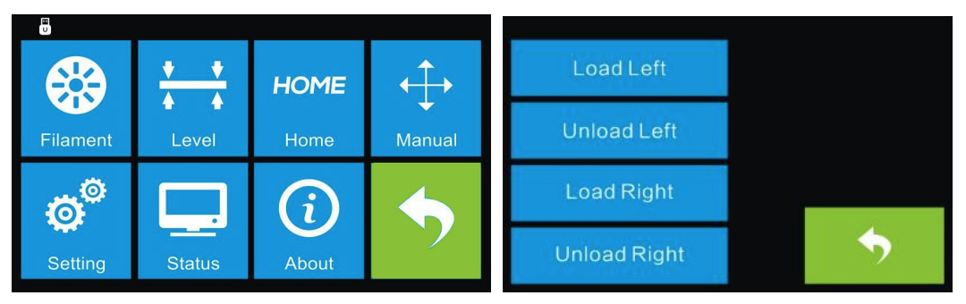
From the main menu, tap the right icon labeled Tool. Tap Filament and Load Left. Keep in mind that you could also load the right extruder if need be.
Wait for the extruder to heat up to the operating temperature. The extruder will alert you once it is at the operating temperature. Load the filament by inserting it into the extruder at an upright angle.
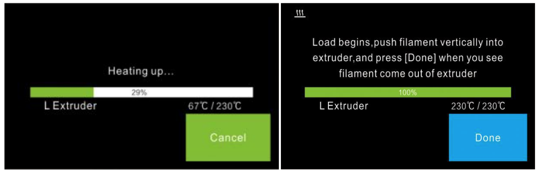
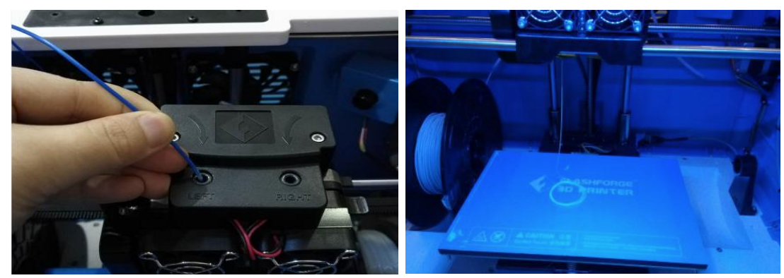
Filament will start to extrude out of the nozzle. Continue loading to ensure that the filament is extruding in a straight line. Then tap Done to finish loading.
Unloading filament
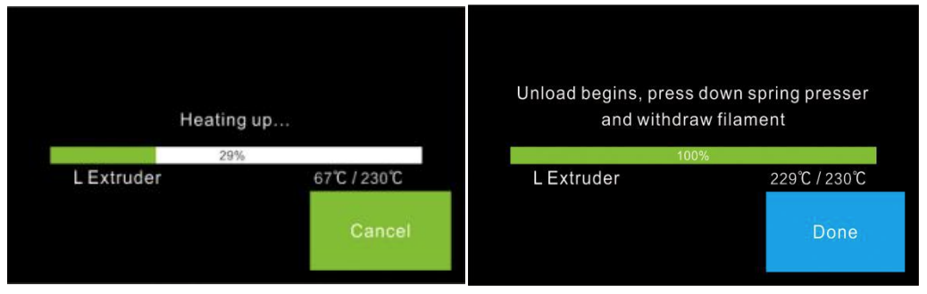
Remove the lid of the Inventor. From the main menu, tap the right icon labeled Tool. Tap Filament and Unload Left
Wait for the extruder to heat up to the operating temperature. The extruder will
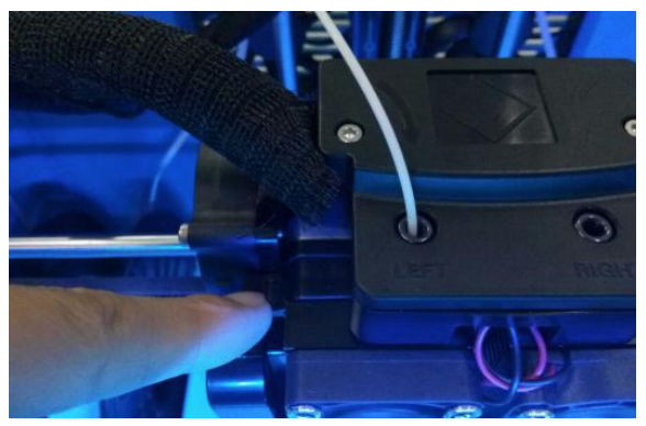
alert you once it is at the operating temperature. Unload the filament by pressing down the spring lever and gently pulling straight up
out of the extruder. Then tap Done to finish unloading. Clip the end of the filament, pull it out of the white tube, place the end in one of the storage holes on the edge of the filament roll. Replace the roll in the correct storage bin and make sure the lid is tightly sealed.
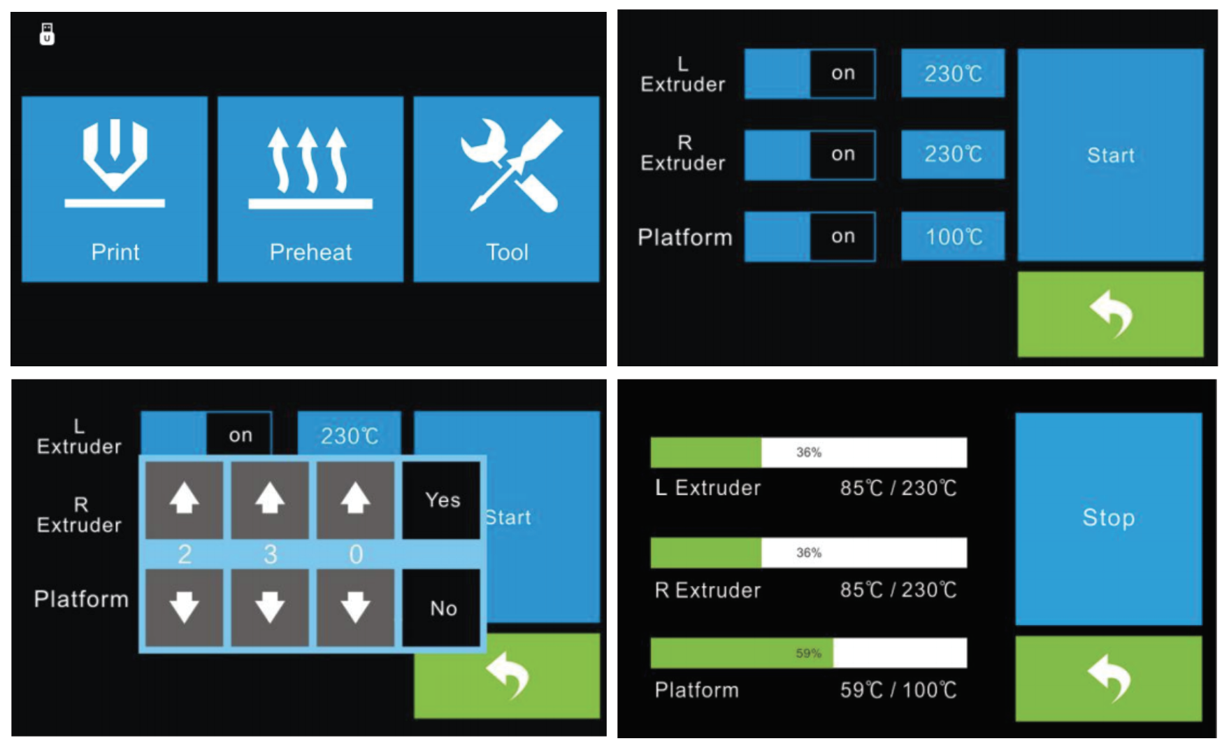
Preheat Option
Tap the Preheat button to enter the preheat interface. Tap the Start button to heat up to the setting temperature. The default temperature is 190C. Tap the temperature display bar to set the temperature. To set the preheat temperature. Tap Yes to save the setting while tap No to cancel the setting. The picture displays the preheat interface. It shows the actual temperature and the target temperature. Tap the Stop button to abort the preheat job.
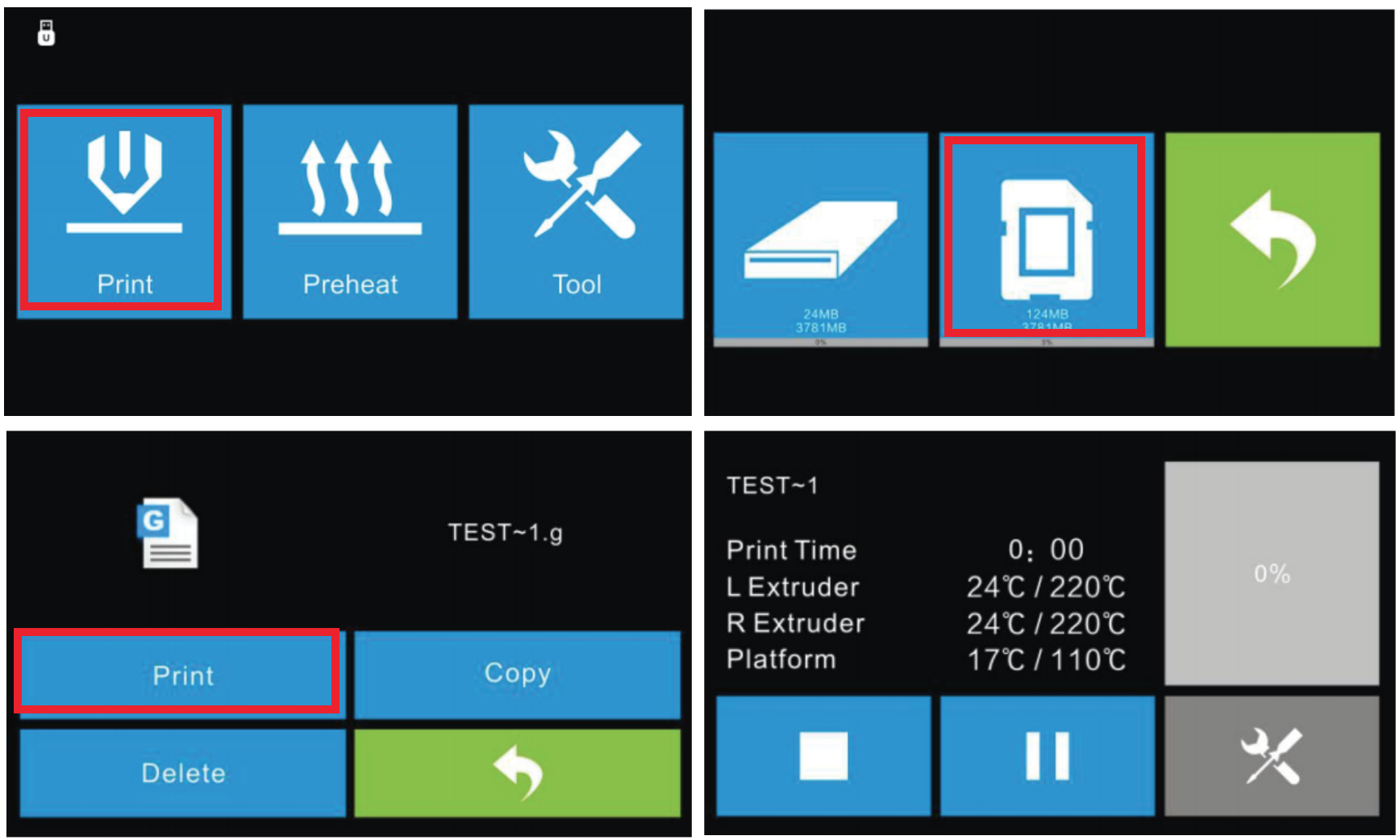
Printing
Read the print file from the local memory SD card. Select the target print file among the list then select Print to begin printing. On the print interface you have the option to abort, pause/resume, or enter the tools menu (To change filament and turn on/off camera).
Finishing
You should be able to gently remove the finished product from the build plate. There are also metal spatulas available to help lift up the edge. It may also be advisable to preheat the bed to allow for easier removal.